
Home IoT Hub Series · 02
Building the Brain — Assembling the IoT Hub Body with an ESP8266 + OLED + Buzzer
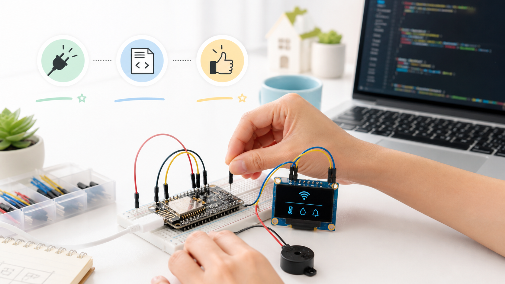
In Part 1 we drew the whole picture. Now we actually build it. No soldering — copy-paste the code and you're done.
Parts and cost
| Part | Qty | Unit price (approx. USD) | Notes |
|---|---|---|---|
| NodeMCU v3 (ESP8266) | 1 | ~$1.70 | The brain body. A D1 Mini works too |
| SSD1306 128×64 OLED (I2C) | 1 | ~$1.20 | 0.96" white |
| Piezo buzzer | 1 | ~$0.20 | 3–5V active type |
| Jumper wires (female-female) | 6 | ~$0.35 | |
| Breadboard | 1 | ~$1.00 | Skip it and wire direct |
| Micro USB cable | 1 | ~$0.70 | Power + code upload |
| Total | ~$5.00 |
Pin wiring
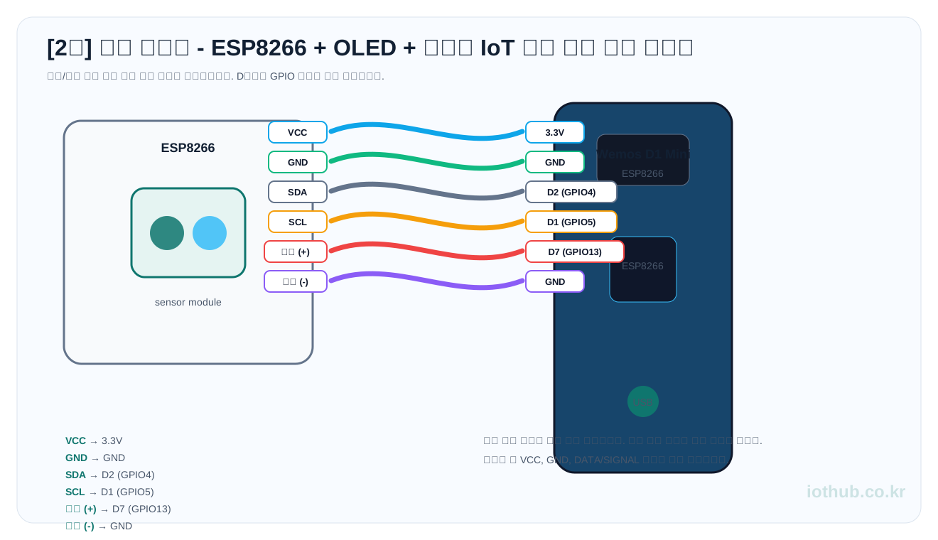
No breadboard needed — wire it straight up with jumper wires. The NodeMCU pin numbers are printed right on the front of the board as D2, D5, and so on, so just plug them in as labeled.
| Sensor/module | Board connection |
|---|---|
| VCC | 3.3V |
| GND | GND |
| SDA | D2 (GPIO4) |
| SCL | D1 (GPIO5) |
| Buzzer (+) | D7 (GPIO13) |
| Buzzer (-) | GND |
D2 and D1. Just remember that the D-prefixed labels and the GPIO numbers are different. Wire it straight from the table above and you won't get confused.First: install the libraries
Open the Arduino IDE and, under Tools → Manage Libraries, install these two.
| Library | Search term |
|---|---|
| Adafruit SSD1306 | Adafruit SSD1306 |
| Adafruit GFX Library | Adafruit GFX |
You also need the ESP8266 board manager installed. If it isn't, paste the address below into Arduino → Preferences → Additional Boards Manager URLs, then install ESP8266 from Tools → Board → Boards Manager.
https://arduino.esp8266.com/stable/package_esp8266com_index.json
🚨 Before you upload — do this first!!
Copy the code below into the Arduino IDE, then change just two spots. Never just upload it as-is. If you don't change them, it won't connect to Wi-Fi.
const char* ssid     = "YOUR_SSID";     // ← your home router's name here
const char* password = "YOUR_PASSWORD"; // ← your home router's password here
>
const char* ssid = "MyHome_2G";>
const char* password = "abcd1234";>
Full code
Once you've changed the SSID and password, copy-paste the rest exactly as-is.
#include <ESP8266WiFi.h>
#include <ESP8266WebServer.h>
#include <Wire.h>
#include <Adafruit_GFX.h>
#include <Adafruit_SSD1306.h>

// =============================================
// 1. Wi-Fi settings (fill these in yourself!)
// =============================================
const char* ssid     = "YOUR_SSID";     // home router name
const char* password = "YOUR_PASSWORD"; // home router password

// Own AP settings for the sensor nodes
const char* ap_ssid     = "IoT_Hub_Net";
const char* ap_password = "iothub1234"; // password for sensor nodes to connect

// =============================================
// 2. Hardware pins
// =============================================
#define BUZZER_PIN    13  // D7 (GPIO13)
#define SCREEN_WIDTH 128
#define SCREEN_HEIGHT 64
#define OLED_ADDR    0x3C

Adafruit_SSD1306 display(SCREEN_WIDTH, SCREEN_HEIGHT, &Wire, -1);
ESP8266WebServer server(80);

// =============================================
// 3. 20 memory slots
// =============================================
#define SLOT_COUNT 20
String slot[SLOT_COUNT] = {
  "--", "--", "--", "--", "--",
  "--", "--", "--", "--", "--",
  "--", "--", "--", "--", "--",
  "--", "--", "--", "--", "--"
};

const char* label[SLOT_COUNT] = {
  "Living Temp","Living Hum","Outside Temp","AC",
  "Boiler","Stove","Gas Leak","Fire",
  "Front Door","Door Lock","Living Light","Fridge Temp",
  "CO2","Dust PM2.5","Power","Water",
  "Hot Water","Rain","Bath Hum","Pet Bowl"
};

// =============================================
// 4. Timer variables
// =============================================
unsigned long lastScroll = 0;
unsigned long lastBuzzer = 0;
int scrollOffset = 0;
const int ITEMS_PER_PAGE = 4;
const int SCROLL_INTERVAL = 3000;
bool warningActive = false;

// =============================================
// setup
// =============================================
void setup() {
  Serial.begin(115200);

  // Buzzer init
  pinMode(BUZZER_PIN, OUTPUT);
  digitalWrite(BUZZER_PIN, LOW);

  // OLED init
  Wire.begin(4, 5); // SDA=D2(GPIO4), SCL=D1(GPIO5)
  if (!display.begin(SSD1306_SWITCHCAPVCC, OLED_ADDR)) {
    Serial.println("OLED init failed");
    while (1) yield();
  }
  display.clearDisplay();
  display.setTextColor(WHITE);
  display.setTextWrap(false);

  // Boot logo
  display.setTextSize(1);
  display.setCursor(10, 20);
  display.println("IoT Hub v2.0");
  display.setCursor(15, 40);
  display.println("iothub.co.kr");
  display.display();
  delay(1000);

  // ── Wi-Fi: connect to the home router in STA mode ──
  WiFi.mode(WIFI_AP_STA); // AP + STA simultaneous mode
  WiFi.begin(ssid, password);

  display.clearDisplay();
  display.setCursor(0, 0);
  display.println("WiFi connecting...");
  display.display();

  Serial.print("Connecting to WiFi");
  int dots = 0;
  while (WiFi.status() != WL_CONNECTED) {
    delay(500);
    Serial.print(".");
    display.setCursor(dots * 6, 16);
    display.print(".");
    display.display();
    dots++;
    if (dots > 20) dots = 0; // fake a line break
  }
  Serial.println();
  Serial.print("STA IP: ");
  Serial.println(WiFi.localIP());

  // ── Soft AP: create own WiFi for the sensor nodes ──
  WiFi.softAP(ap_ssid, ap_password);
  Serial.print("AP  IP: ");
  Serial.println(WiFi.softAPIP());

  // ── Web server routing ──
  server.on("/set", handleSet);
  server.on("/", handleRoot);
  server.on("/status", handleStatus);
  server.onNotFound(handleNotFound);
  server.begin();
  Serial.println("HTTP server started");

  // ── Show the IP on the OLED ──
  display.clearDisplay();
  display.setTextSize(1);
  display.setCursor(0, 0);
  display.println("IoT Hub Ready");
  display.setCursor(0, 14);
  display.print("LAN: ");
  display.println(WiFi.localIP());
  display.setCursor(0, 28);
  display.print("AP : ");
  display.println(WiFi.softAPIP());
  display.setCursor(0, 46);
  display.println("/set?no1=25.5");
  display.println("  to send data");
  display.display();
  delay(3000);
}

// =============================================
// loop
// =============================================
void loop() {
  server.handleClient();
  updateOLED();
  updateBuzzer();
}

// =============================================
// Check warning state
// =============================================
bool checkWarning() {
  for (int i = 0; i < SLOT_COUNT; i++) {
    // slots 7 (gas leak), 8 (fire), 9 (front door open) → warn if not 0
    if ((i == 6 || i == 7 || i == 8)
        && slot[i] != "0" && slot[i] != "--") {
      return true;
    }
    // slot 20 (dog food bowl) → warn if under 50g
    if (i == 19 && slot[i] != "--" && slot[i].toInt() < 50) {
      return true;
    }
  }
  return false;
}

// =============================================
// Buzzer control (beep every 500ms when warning)
// =============================================
void updateBuzzer() {
  warningActive = checkWarning();
  if (warningActive) {
    unsigned long now = millis();
    if (now - lastBuzzer < 500) return;
    lastBuzzer = now;
    digitalWrite(BUZZER_PIN, !digitalRead(BUZZER_PIN));
  } else {
    digitalWrite(BUZZER_PIN, LOW);
  }
}

// =============================================
// GET /set?no1=value&no2=value ...
// =============================================
void handleSet() {
  int updated = 0;
  for (int i = 1; i <= SLOT_COUNT; i++) {
    String paramName = "no" + String(i);
    if (server.hasArg(paramName)) {
      slot[i - 1] = server.arg(paramName);
      updated++;
      Serial.printf("Slot %d (%s) <- %s\n",
                    i, label[i - 1], slot[i - 1].c_str());
    }
  }
  String msg = "{\"updated\":" + String(updated) + "}";
  server.send(200, "application/json", msg);
}

// =============================================
// GET /  → HTML dashboard
// =============================================
void handleRoot() {
  String html = "<!DOCTYPE html>\n"
  "<html lang=\"ko\">\n"
  "<head>\n"
  "<meta charset=\"UTF-8\">\n"
  "<meta name=\"viewport\" content=\"width=device-width,initial-scale=1.0\">\n"
  "<title>IoT Hub</title>\n"
  "<style>\n"
  "*{margin:0;padding:0;box-sizing:border-box;}\n"
  "body{font-family:system-ui,sans-serif;background:#1a1a2e;color:#eee;padding:16px;}\n"
  "h1{text-align:center;font-size:1.3rem;margin-bottom:4px;color:#e94560;}\n"
  ".sub{text-align:center;font-size:0.7rem;color:#555;margin-bottom:16px;}\n"
  ".grid{display:grid;grid-template-columns:repeat(auto-fill,minmax(185px,1fr));gap:10px;}\n"
  ".card{background:#16213e;border-radius:8px;padding:12px;border-left:4px solid #0f3460;}\n"
  ".card.warn{border-left-color:#e94560;background:#1c0e1a;}\n"
  ".card .no{font-size:0.6rem;color:#555;margin-bottom:2px;}\n"
  ".card .label{font-size:0.8rem;color:#a0a0b0;margin-bottom:4px;}\n"
  ".card .value{font-size:1.2rem;font-weight:700;}\n"
  ".footer{text-align:center;margin-top:16px;font-size:0.7rem;color:#444;}\n"
  "</style>\n"
  "</head>\n"
  "<body>\n"
  "<h1>IoT Hub</h1>\n"
  "<div class=\"sub\">iothub.co.kr</div>\n"
  "<div class=\"grid\">\n";

  for (int i = 0; i < SLOT_COUNT; i++) {
    bool isWarn = false;
    String val = slot[i];
    if ((i == 6 || i == 7 || i == 8) && val != "0" && val != "--") isWarn = true;
    if (i == 19 && val != "--" && val.toInt() < 50) isWarn = true;

    html += "<div class=\"card" + String(isWarn ? " warn" : "") + "\">";
    html += "<div class=\"no\">#" + String(i + 1) + "</div>";
    html += "<div class=\"label\">" + String(label[i]) + "</div>";
    html += "<div class=\"value\">" + val + "</div>";
    html += "</div>\n";
  }

  html += "</div>\n"
  "<div class=\"footer\">30s auto-refresh | IoT Hub on ESP8266</div>\n"
  "<script>setTimeout(()=>location.reload(),30000);</script>\n"
  "</body>\n</html>";

  server.send(200, "text/html; charset=utf-8", html);
}

// =============================================
// GET /status → JSON
// =============================================
void handleStatus() {
  String json = "{";
  for (int i = 0; i < SLOT_COUNT; i++) {
    if (i > 0) json += ",";
    json += "\"no" + String(i + 1) + "\":\"" + slot[i] + "\"";
  }
  json += ",\"warning\":" + String(warningActive ? "true" : "false") + "}";
  server.send(200, "application/json", json);
}

// =============================================
// 404
// =============================================
void handleNotFound() {
  server.send(404, "text/plain",
    "404 - Use /set?no1=value  or  /  or  /status");
}

// =============================================
// OLED auto-scroll + invert on warning
// =============================================
void updateOLED() {
  unsigned long now = millis();
  if (now - lastScroll < SCROLL_INTERVAL) return;
  lastScroll = now;

  display.clearDisplay();

  // Top bar
  display.setTextSize(1);
  display.fillRect(0, 0, SCREEN_WIDTH, 10, WHITE);
  display.setTextColor(BLACK);
  display.setCursor(2, 1);
  display.printf("IoT Hub [%d/%d]",
    scrollOffset / ITEMS_PER_PAGE + 1,
    (SLOT_COUNT + ITEMS_PER_PAGE - 1) / ITEMS_PER_PAGE);
  display.setTextColor(WHITE);

  // Body: 4 at a time
  for (int i = 0; i < ITEMS_PER_PAGE; i++) {
    int idx = scrollOffset + i;
    if (idx >= SLOT_COUNT) break;

    int y = 14 + i * 12;
    String val = slot[idx];

    bool isWarn = false;
    if ((idx == 6 || idx == 7 || idx == 8) && val != "0" && val != "--")
      isWarn = true;
    if (idx == 19 && val != "--" && val.toInt() < 50)
      isWarn = true;

    display.setCursor(0, y);
    display.print(label[idx]);
    display.print(":");

    if (isWarn) {
      display.fillRect(80, y, SCREEN_WIDTH - 80, 8, WHITE);
      display.setTextColor(BLACK);
    }
    display.setCursor(82, y);
    display.print(val);
    display.setTextColor(WHITE);
  }

  display.display();

  scrollOffset += ITEMS_PER_PAGE;
  if (scrollOffset >= SLOT_COUNT) scrollOffset = 0;
}
Upload
1. Connect the NodeMCU to your PC with the USB cable. 2. In the Arduino IDE, choose Tools → Board → ESP8266 Boards → NodeMCU 1.0. 3. Select the port and click the Upload (→) button. 4. Once the upload finishes, open Tools → Serial Monitor. Set the baud rate to 115200.
What to check
If the serial monitor prints something like this, you're good:
Connecting to WiFi...
STA IP: 192.168.0.50
AP  IP: 192.168.1.1
HTTP server started
The OLED also shows the two IPs, alternating.
STA IP(something like 192.168.0.50) → the address assigned by your home router. Visit this address from a PC/phone on the same network and the HTML dashboard comes up.AP IP(192.168.1.1) → the address ofIoT_Hub_Net, the Wi-Fi the brain creates itself. From now on, the sensor nodes send their data here.
Tests (be sure to run all of them)
1) Check the HTML dashboard: From a PC browser, go to http://<STA IP> (e.g. http://192.168.0.50). If a grid of 20 cards appears on a dark background, all showing --, it's working.
2) Push a value in: Type this into the browser address bar:
http://<STA IP>/set?no1=24.5&no2=58
If it responds with {"updated":2}, it worked. Refresh the dashboard and cards #1 and #2 will have changed to 24.5 and 58.
3) Alert test:
http://<STA IP>/set?no7=1
Card #7 (Gas Leak) gets highlighted red, and the buzzer beeps every 0.5 seconds. On the OLED, the #7 label shows inverted too.
http://<STA IP>/set?no7=0
Set it back to 0 and the buzzer switches off and the card returns to its original color.
4) Food-bowl alert test:
http://<STA IP>/set?no20=30
Put 30g into #20 (Pet Bowl) — it's under 50g, so the alert fires.
http://<STA IP>/set?no20=120
Raise it to 120g and the alert clears.
5) Check the Wi-Fi AP: In your phone's Wi-Fi settings, check that IoT_Hub_Net shows up. You should be able to connect with the password iothub1234. Connecting is all that matters — there's no internet (that's by design).
Checkpoints when it doesn't work
Don't just re-upload blindly — check the following in order. 90% of problems get solved right here.
The upload itself won't go through
| Symptom | Cause | Fix |
|---|---|---|
Compilation error: Adafruit_GFX.h not found | Library not installed | In Tools → Manage Libraries, install Adafruit GFX and Adafruit SSD1306 |
Compilation error: ESP8266WiFi.h not found | ESP8266 board manager not installed | Add https://arduino.esp8266.com/stable/package_esp8266com_index.json to the Arduino preferences, then install ESP8266 from the boards manager |
esptool.FatalError: Failed to connect | Wrong port / driver issue | ① Check the USB cable is a data cable (charge-only cables won't work). ② In Tools → Port, select the port where the NodeMCU shows up. ③ Still stuck? Reboot the PC and try again |
Stalls at Upload error: 0% | Failed to enter GPIO0 flash mode | The NodeMCU normally enters flash mode on its own, but if it doesn't, hold down the board's FLASH button just before uploading and release it once the upload starts |
It uploaded, but it's behaving strangely
| Symptom | Cause | Fix |
|---|---|---|
| OLED doesn't light up at all | Wiring error | Check VCC→3.3V, GND→GND. Check SDA/SCL are properly seated on D2/D1. Plugging into 5V can fry the OLED, so use 3.3V for sure |
| OLED lights up but shows no text | I2C address error | Try changing OLED_ADDR 0x3C on line 83 to 0x3D. Some SSD1306s use a different address |
OLED shows "IoT Hub Ready" but STA IP: 0.0.0.0 | Wi-Fi connection failed | SSID/password typo. Check case and special characters especially. Won't work if the router only supports 5GHz (ESP8266 is 2.4GHz only). Make sure 2.4GHz is enabled in the router settings |
Got a STA IP but can't reach / | Firewall / different subnet | Check the PC is on the same router. Check the PC's IP is in the 192.168.0.xxx range (the first three groups must match). Won't work if you're on a hotspot or a VPN is on |
| Buzzer doesn't sound | Reversed polarity or defective | Check the buzzer's + is on D7 and - is on GND. A passive buzzer instead of an active one may make no sound, so make sure it's an active buzzer |
| Serial monitor shows garbled characters | Baud rate mismatch | Check the baud rate at the bottom-right of the serial monitor is 115200. If it's set to 9600, it all comes out garbled |
| Everything's fine but the HTML dashboard is very slow | ESP8266 CPU overload | Normal. The ESP8266 isn't a server built to handle dozens of requests a second. The dashboard auto-refreshes every 30 seconds, so it's fine. /set requests are handled within tens of ms |
What we've done so far
- We put an OLED and a buzzer on a single ESP8266.
- A web server is up, and you can write data into the 20 slots with
/set?no1=value. - The HTML dashboard comes up, and the OLED auto-scrolls four at a time.
- The buzzer reacts to gas, fire, intrusion, and food-bowl alerts.
- The brain's own Wi-Fi
IoT_Hub_Net, for the sensor nodes to join, is ready too.
It's still full of --, but the brain is done. Starting tomorrow, we attach the sensors one at a time.
Distributed edge-node build list
The next steps fill the 20 memory slots of this brain server with distributed edge nodes. Each sensor node joins IoT_Hub_Net and updates a central NodeMCU server slot through the /set?noX=value endpoint.
What's next
Next time we add the living-room temperature/humidity sensor. A DHT22 + Wemos D1 Mini combo. We'll cover the setup where a temperature reading taken in a far corner of the living room rides IoT_Hub_Net back to the brain.
This article is part of the 20-channel Home IoT system built from the Part 2 central brain server and the distributed edge nodes in Parts 3-19. Use this map to check the slot and sensor flow across the series.
[Part 1] Home IoT Hub overview[Part 2] Central brain server · slots 1-20[Part 3] Stop guessing room comfort · slots 1/2[Part 4] Did I close the door? · slots 9[Part 5] Is the fridge really cooling? · slots 12[Part 6] Should I open the window? · slots 3[Part 7] Stop bathroom mold before it starts · slots 19[Part 8] Is the boiler actually running? · slots 5/17[Part 9] Did I leave the gas stove on? · slots 6[Part 10] Get warned before gas smell becomes obvious · slots 7[Part 11] Catch flame signs while away from home · slots 8[Part 12] Is bad air making you foggy? · slots 13/14[Part 13] Why is the power bill so high? · slots 15[Part 14] Is water leaking, and how much are we using? · slots 16[Part 15] Do not leave windows open in the rain · slots 18[Part 16] Are the lights off and the door locked? · slots 11/10[Part 17] Control the air conditioner from the IoT hub · slots 4[Part 18] Is the dog bowl empty? · slots 20[Part 19] Cool the room only when someone is there · slots 1/4[Part 20] The house finally fits on one screen · slots all